Blockly Bot

Intro
Blockly Bot is a universal robotics platform that I am building for the Perot TECH Truck. It will be built around an Arduino Nano and it will be programed using a graphical block-based programming language called ArduBlockly. The goal of this project is to create an educational platform to teach kids about coding, microcontrollers, electronics, and more.
Ardublockly


What is Ardublockly?

What is Ardublockly?
Ardublockly is an easy to use, block-based programing environment for kids to use to program Arduino microcontrollers. It is based on an open source project from google called blockly, which allows developers to easily insert block programming tools into their projects. There are several benefits to using this type of development environment when teaching kids. First off it allows the kids to program in an intuitive way using blocks that fit together in a specific way to prevent errors. Also, one of the features of blockly is that it allows you to see the arduino code that is being written in real time. This allows kids to compare the block code that they write to the C code that is being sent to the arduino. The ardublockly project is run by gitHub user carlosperate and if you would like to try an example of ardublockly you can do so by clicking here.
Changes Made
In order to make Ardublockly easy to use for programming the blockly bot, some slight changes where made to the Ardublockly source code. First I had to add some new blocks to control the different functions of blockly bot like the motors and the ultrasonic sensors. To add the blocks for the ultrasonics I used the blockly block editor provided by Google to design the block itself and add the inputs it required. Once the block is designed it must be added to the toolbox on the left side of the Ardublockly interface by editing the toolbox XML file. Then a code generator must be created for that block. The code generator is a javascript file that tells ardublockly what Arduino code corresponds to this block and how the different inputs should change that code. Once this final step is complete the block appeared in the toolbox and functioned like any other block. Setting up the block for the robots motors was a bit different. Creating the code generator and the block itself was simple because blockly bot uses continuous rotation servo motors. This allowed me to simply duplicate the pre existing block for controlling servo motors and modify it for my purposes. One of the modifications I made was to add a trim function in the code generator. Because of the way the continuous rotation servo motors work, sometimes they move slowly when they are supposed to be stopped. This trim function allows you to change some numbers in an XML file to adjust the stopping point of the motors, fixing this issue.
The Electronics

The Sensors

Blocklybot contains a host of sensors including two photoresistors, two line following sensors, and an ultrasonic sensor. As with all of the functions built in to Blocklybot the sensors allow us to accomplish certain educational goals. The photoresistors teach about analog read, the line following sensors teach about digital read, and the ultrasonic sensors teach about different libraries that can add functionality to the arduino.
The Motors
The motor that I chose for Blocklybot is a 9 gram continuous rotation servo motor. I picked this motor because it is very small, cheap, and easy to control. With most other motors some sort of motor controller would be necessary. However, the servo has the motor controller built in. The only problem is that continuous rotation servo motors are hard to find so I ended up modifying a 180 degree servo to rotate 360 degrees. To do this I removed the potentiometer that monitors the position of the servo and installed a voltage divider so that the servo always thinks it is pointed at 90 degrees. That way when you tell it to go to 180 degrees it will rotate to try to get to 180 degrees but because it always thinks its stuck at 90 it will just rotate forever.
Programming

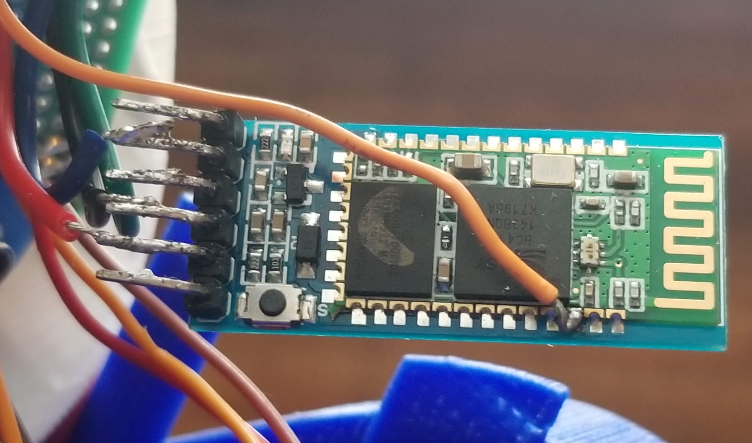
When designing Blocklybot one thing I had to consider was how it would be programmed. I considered for a bit whether or not to just have a long usb cable running to the robot. However, I eventually decided that the cable would end up getting in the way of the robot and be tripping hazard for the kids. This eventually led me to seek wireless options like bluetooth for programming the robot. Through my research I found that the HC-05 bluetooth module could be used to program the arduino wirelessly. This was as simple as soldering a wire to the KEY pin on the HC-05 module and connecting it to the reset pin of the arduino and using AT commands to change the settings of the bluetooth module to allow it to program the arduino.
The PCB
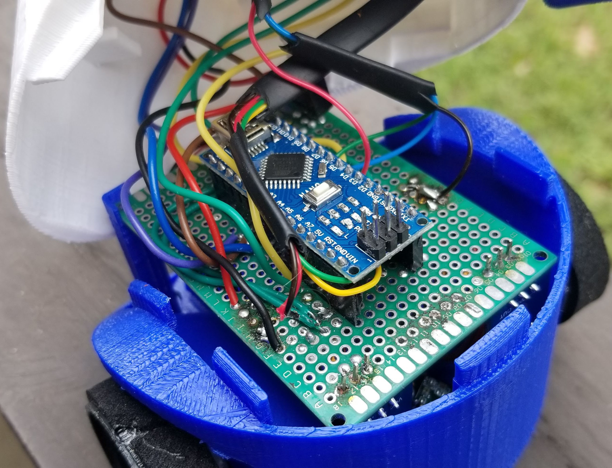
Because I would need to make multiple Blocklybots I realized it would be difficult to wire every robot using prototyping board. My solution was to try my hand at creating my own PCBs. The method I used is often referred to as the laser paint method. This method entails spray painting the copper side of a copper clad board and using a laser cutter to burn away the paint where the copper needs to be etched away. Then the board is placed in ferric acid to remove the copper before using acetone to remove the excess paint. The resulting board is a bit rough around the edges however, it should work for my purposes. I designed the board in KiCAD which was definitely a learning experience for me. However, despite my inexperience, the board turned out quite good.
Other Features
Blocklybot also includes several other features that allow the kids to interact with it in different ways. One of these features include an RGB LED on the front of the robot. This allows kids to learn about analogwrite and using pwm to fade an LED. This also allows the kids to troubleshoot and change the color of the LED based on the mode of the robot. The robot also features a set of 5 buttons on its back that allow the user to program functions that run based on button presses. This was inspired by another set of educational robots often used by the TECH truck called Bee-bots which cost $100 a piece. Hopefully Blockly bots will be able to replace the expensive Bee-bots in the future.
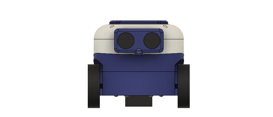
The 3D Printed Shell
The main shell of the robot is comprised of nine parts all of which are 3D printed in PLA plastic. When designing the robot one of my main objectives was to make the robot cute and approachable for kids. I also wanted a design that would allow for showing off the arduino inside the robot. This led to the sort of clam shell design shown above. This design has a face giving it some personality that kids really resonate with. It can also easily be opened and closed being held together by friction-fit tabs. This keeps the robot approachable for kids to program but also highlights the engineering on the inside. The entire robot was modeled in Autodesk Fusion 360 before anything was assembled. I started by modeling the the PCB at the heart of the robot. Then I designed the shell to encase the PCB occasionally printing test prints to validate my design.