Paper Circuits

Introduction
I designed this program for the Perot TECH Truck in order to teach kids in the DFW area about simple electronics skills. Some of the skills the kids learn include reading circuit diagrams, the function of various electronic components, and how to solder the components together. This simple project will hopefully inspire kids to become tinkerer's in their daily lives and pursue a future in electronics.
The Concept
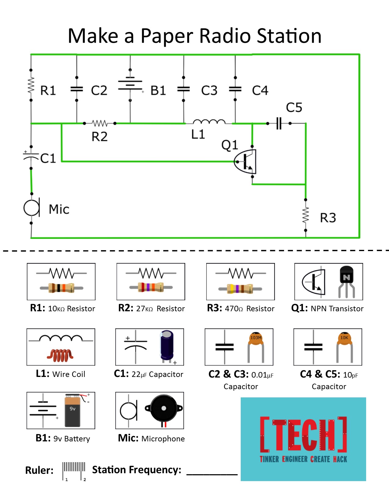
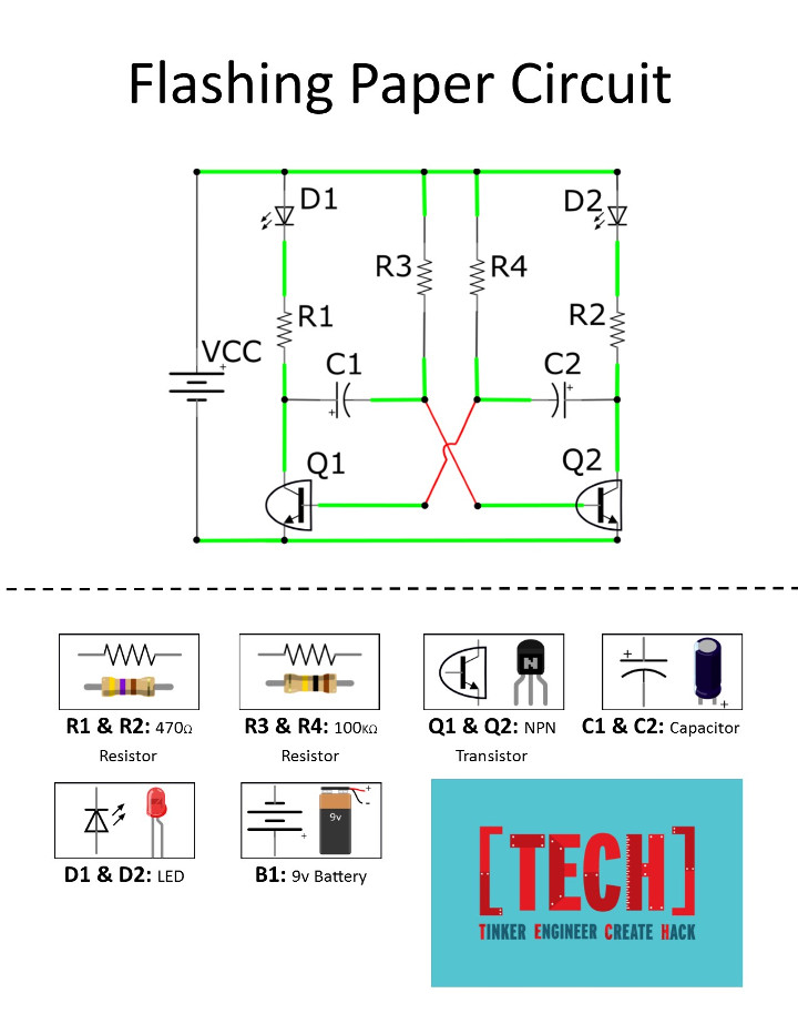
For this project every kid gets a piece of paper with a circuit diagram and a list of components. The component list has a picture of each component, the circuit diagram symbol, as well as the name and value of the component. This way the participants can see what the part actually looks like and how it is represented in a circuit diagram. The diagram on the handout has the traces highlighted in green for the kids to outline with copper tape. Then the kids take the components from the component list and match that component with the symbol in the circuit diagram. Finally, they solder each part in place resulting in a working circuit.
Paper Radio

The Paper Radio Circuit is what I initially designed this program around and it is based on a project from Make Magazine. The function of this circuit is to be able to transmit an audio signal from a connected microphone or cell phone over radio waves to a nearby radio. This circuit contains resistors, transistors, an inductor, and both ceramic and electrolytic capacitors. The variety of components and the usefulness of this circuit was a real draw for using it in this project. However, it ended up also being a detriment. The thought process was that with the different components would offer plenty of opportunities for teaching, but it ended up being a bit too complicated. Also, while the circuit was useful, it was hard to see when it was working. To combat this, we purchased a software defined radio so we could scan through all of the radio signals and find where the circuit was transmitting. But, because of the lack of immediate feedback and the complexity of the project, I decided to ditch this circuit for the flashing circuit outlined below.
Paper Flashing Circuit

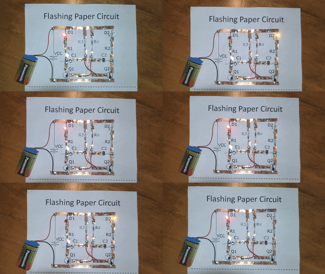
The Flashing Circuit is the final form of this project. The circuit is a simple astable multivibrator that flashes two LEDs back and forth at a speed determined by two capacitor values. Unlike the radio project this circuit only contains resistors, capacitors, LEDs, and transistors greatly reducing the complexity of the project. Also, because the end result of this project is a flashing light, it is much easier to see when it is working. The process for this project is very similar to the one above. First, the participants outline the traces of the circuit diagram with copper tape. Then they solder all the components in place. Although the is circuit is relatively simple the type of components used allow for education on a variety of topics. The led and the capacitor allow us to introduce polar components while also discussing the functions of those components. The resistors allow us to talk about the importance of limiting current to the led. And the transistors allow us to talk about switching with transistors and their applications in everyday electronics. These lessons and the many more that can be taught through this project will hopefully inspire kids to pursue a hobby in electronics on their own time.