The Perover

Intro
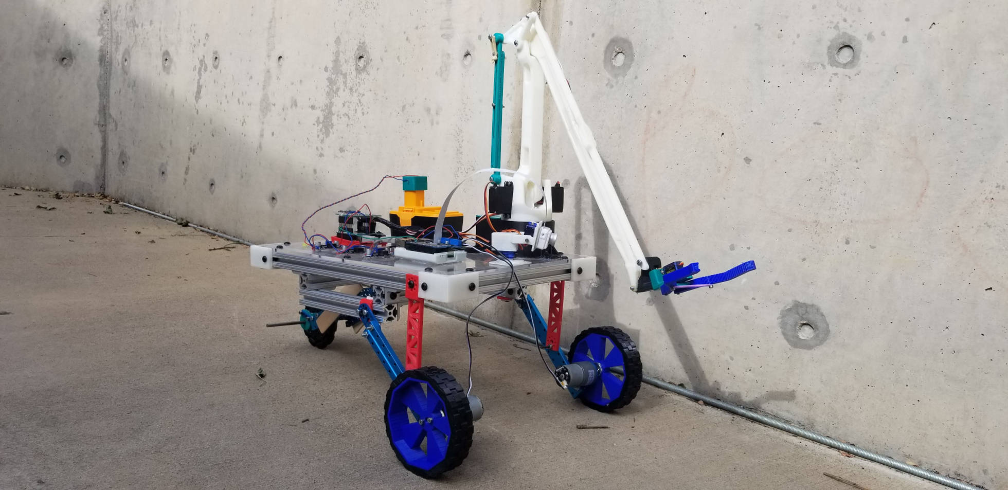
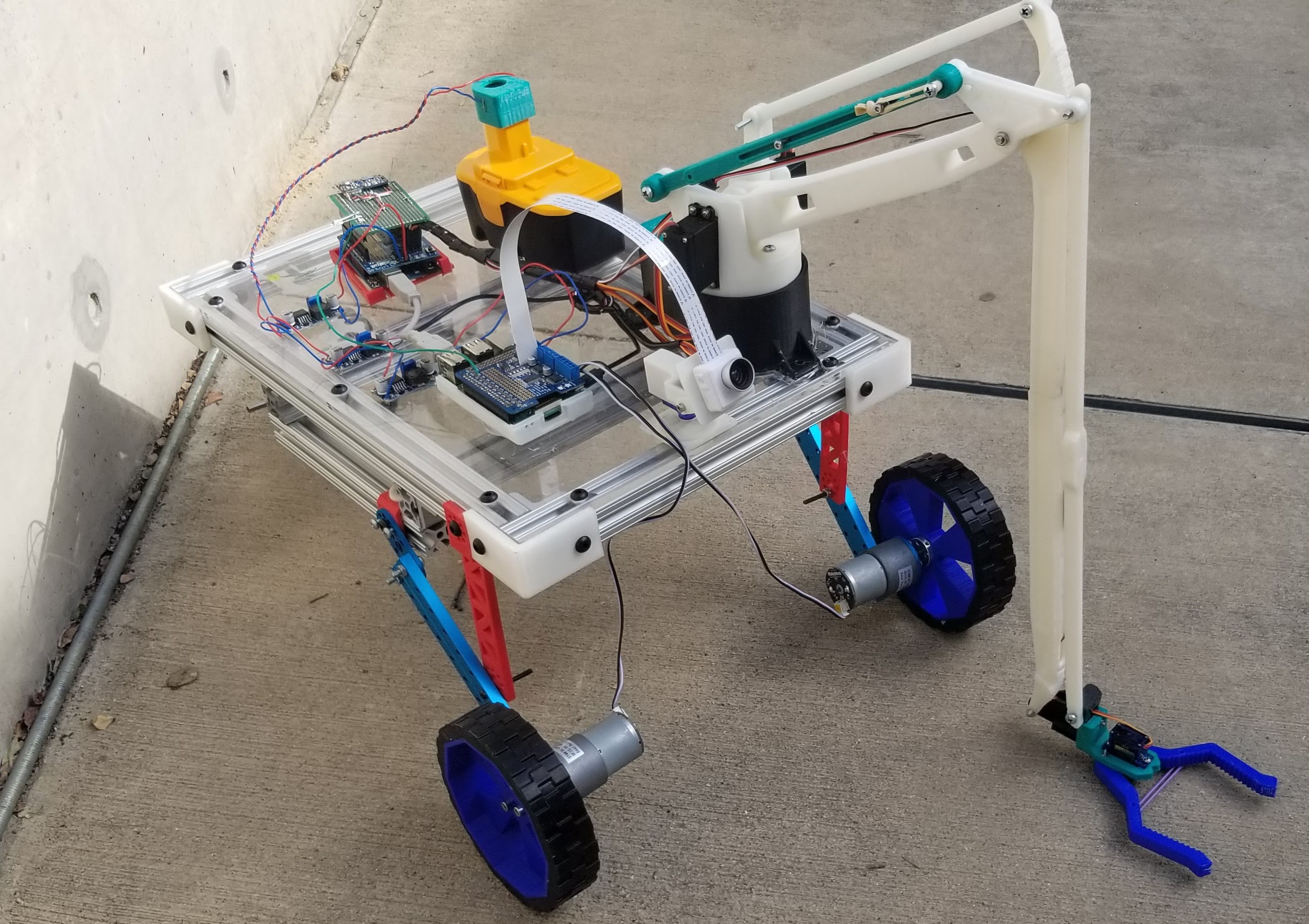
The Perot Tech Truck Rover project is a robotic rover that is meant to spark a conversation with participants about mars rovers and other space dwelling robots. When I started at the Perot the main structure of the robot was in place, it was able to drive and take sensor data but not much else. In the year since I joined the team I have dramatically improved the user interface, added a camera with a pan-tilt system, added a robotic arm to manipulate objects in the field, and I have improved the power system along with the rest of the electronics. In this build log I will document the improvements I make to the robot and chronicle the process as I improve upon its functionality.
The User-Interface
In the Beginning
The initial design of the rover that was in place when I first started at the Perot museum was as follows. first, as the main brains, there was a Raspberry Pi. This little single board computer was responsible for running a python script that would interface with the motor controller that was seated on top of the pi. This python script allowed for control of the robot through an intuitive GUI that would allow the participants to drive the rover around with ease. Connected to the pi via USB was an Arduino. The Arduino's one and only job was to take the data from the sensors and send it back to the pi via the UART so that it could be displayed on the GUI. It was in this initial GUI where I found the first big improvement that could be made. When I got there, they were using remote desktop software to access the desktop of the Raspberry Pi to run the python script and use the GUI. This was a very round about and resource heavy way of controlling the robot, so I made optimizing the user interface my first task.
Redesign One: TCP
In previous projects I had some experience with TCP protocols and how to implement them in applications like this, so I decided to start there. I took the program that was already written and broke it up into a client and a server program. The server program ran on the Raspberry Pi and controlled the motors and sent the sensor data to the client program. The client program ran on the computer that was being used to control the robot. It included the user interface and sent the desired commands from the user to the server to be processed. This approach was much quicker and more reliable than the original, however it did have its flaws. The main flaw being that if any changes were made, then both the client and the server application needed to change also. This caused some trouble in making sure that everyone on the team had the most up to date version of the software. Thus, I decided to move from a python-based application to a web application that could be accessed from any device without the need of special software.
Redesign Two: PHP Web Application
Initially the web application used PHP to control the rover by executing terminal commands that would run various python scripts to move the motors and collect sensor data. I understand that this is by far the least secure way of doing this task and it is a huge security concern in almost any other application. However, because the rover was only ever going to be connected to a dedicated isolated WIFI network I felt that it would be fine. The real downside to this approach was the speed. Using PHP to run python scripts was just way too slow for real time operation of a robotic rover. Thus, I went back to the drawing board to try and find a new alternative. What I found was a communications protocol called MQTT. this protocol uses TCP to communicate very reliably to the server (also sometimes called a broker) and there are many open source libraries to implement MQTT in almost every application. Therefore, this approach would offer the speed of TCP while also allowing me to easily implement it into a web application.
Redesign Three: MQTT Web Application
Today the operation of the rover goes something like this. When the robot is powered on the Raspberry Pi automatically starts a web server. The user can go on to any device connected to the same network, type in the IP address of the pi, and access the control interface for the robot. Here they are greeted with a series of buttons. When the user presses the "start all scripts" button several python scripts are started. These scripts are responsible for listening to the data coming through the MQTT broker and, when the command is received, moving the motors, reading the sensors, etc. Once the scripts have started the user can click on any of the various other buttons which link to a web interface that controls that aspect of the rover. For example, when you click on the rover control button it redirects you to a webpage containing up, down, left, and right arrows to drive the robot around. When one of the robot control web pages is opened the JavaScript within the webpage turns that browser window into a MQTT client. This client can send commands to the rover to operate any one of its functions, and it can receive commands like sensor data to be updated on the screen. The real beauty of this system is that it can be run on any device, it is fast enough for real time operation, and it is robust enough to be adaptable to any functionality we add in the future.
The Camera
The Initial Setup
Initially the rover did not have a camera. The team at the Perot Museum had attempted to install a camera before I had arrived however, because of the low quality of the webcam, they had found it difficult and unreliable. I had previously worked with the Raspberry Pi Camera made by the Raspberry Pi Foundation, so I brought it in to try it out. After adding a bit of code to the TCP client and server interfaces I was able to get the rover to take a picture when a button was pressed. This picture was saved by the server in a folder that was shared by the Raspberry Pi on the local network. Then the client program running on the control computer would constantly check that folder and update the image in the GUI with the most recent copy. I decided to go with this method because, although it wouldn't allow for streaming of live video, it was a way to get the image from the rover to the control station without using too many resources. Using TCP to stream video is generally not recommended and I couldn't find any open source libraries to stream video with python. I could have created my own UDP streaming library however I was already considering switching to a web interface and I know of several software packages that allow for video streaming to a web interface.
The Final System
 For the final camera mechanism, I installed a pan-tilt system so the user could move the camera around independent from the rest of the rover. When the user opens the camera interface they are greeted with a viewport window, so they can see what the camera sees, and a set of arrow buttons to control the pan-tilt mechanism. When they press the arrow buttons it sends an MQTT request to the broker on the Raspberry Pi which gets picked up by the Arduino Listener python script. This script is responsible for handling all the communication to the Arduino over the UART. When it gets the command to move the camera it sends it to the Arduino which has an Adafruit servo shield on it. The Arduino then moves the pan-tilt servos to the correct location. For the video feed in the final camera system I am using a software package called UV4L. Initially I tried MJPEG streamer however I found it to be too slow, especially with multiple streams. UV4L conveniently sets up its own video streaming server, and with their handy RESTful API adding the video stream to the user interface was as easy as adding an image to a webpage.
The Robotic Arm

The Hardware

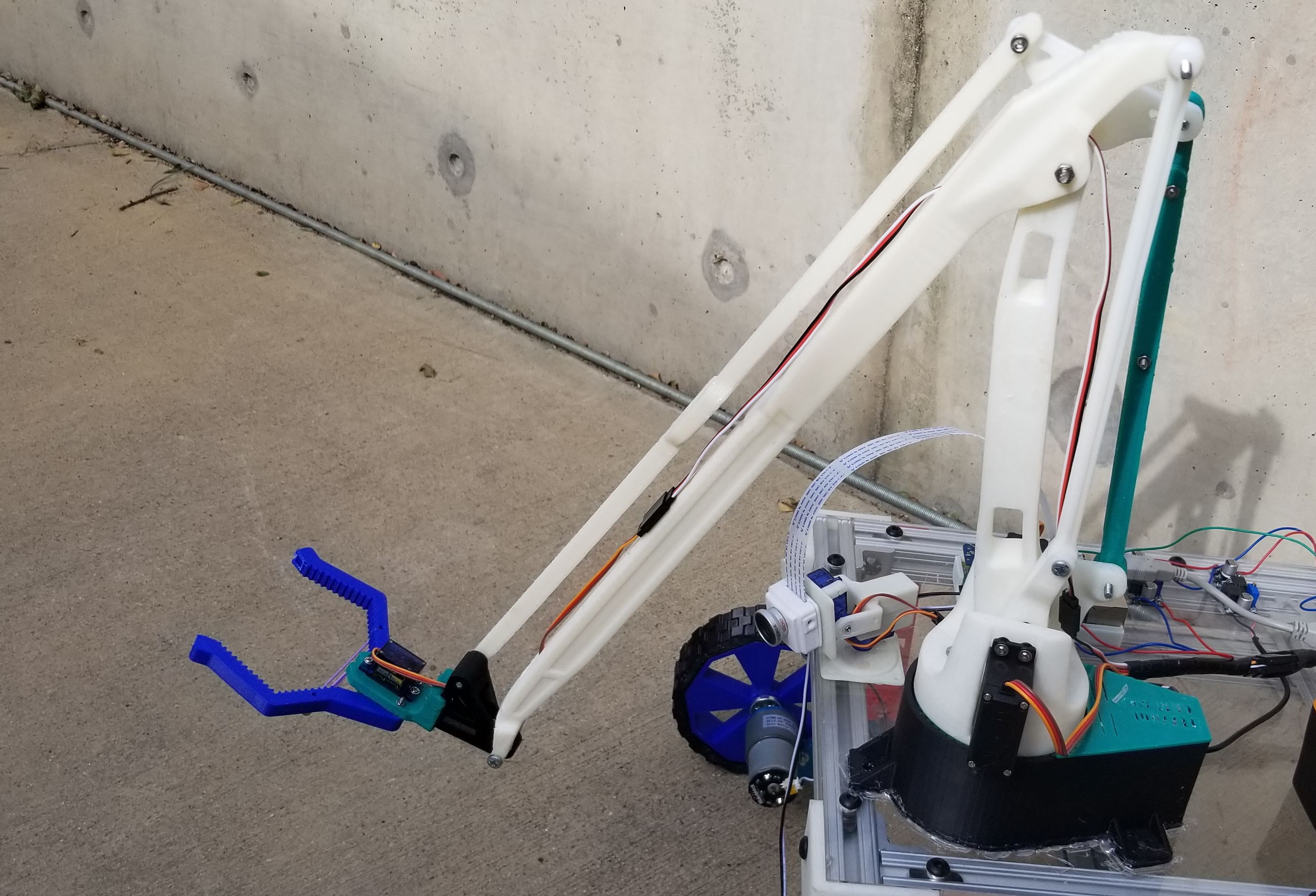
Before I even began working at the Perot Museum I knew I wanted to create a robotic arm for the rover. However, many things needed to come in place ahead of time to make that happen. First, I needed a fast method of communicating with the rover over the wireless network so that it could be controlled in as close to real time as possible. Thankfully the MQTT protocol is fast enough for my purposes. Then I needed to create an arm that would attach securely to the robot but still be able to pick up an object off the floor. I briefly considered creating a secondary platform to get the arm closer to the floor, however, because I've seen how rough kids can be, I eventually decided it would be more secure to attach it to the platform of the rover. Therefore, the linkages of the arm needed to be long, like really long, to reach the floor. The arm mechanism is based on a file I found on Thingiverse.com called EEZYbotARM MK2 and it was entirely 3D printed. There was just one little problem, the original arm was only about 6 inches tall, and wouldn't be able to reach the ground. So, I had to stretch all the linkages to about 4 times their original size without distorting it too much so that I could still use the original nuts and screws to assemble it. After doing that, I just had to assemble all the parts as specified by the original designer. Once assembled I ran into another problem, it turns out the arm was never designed to be able to reach below the base. It was only meant to pick up things that were on the same plane as the base of the arm. Therefore, I had to come up with some way to get the arm to reach all the way to the floor with the base sitting on top of the robot. The solution I came up with was a replacement linkage that could telescope so that it couldn't restrain the arm from reaching the ground. I also attached a rubber band to it to keep it under tension and allow it to still complete its function as a linkage in the system.
The Software
For the camera and driving interfaces I was able to use up, down, left, and right arrows to control the functionality of the rover. However, the robotic arm requires more degrees of freedom to successfully control it, and thus requires a different interface. The interface I decided to use was one that is often used in controlling industrial robotic arms called inverse kinematics. With this method all you need to do is tell the software where you want the end effector of the arm to be, and it calculates the angles of the two linkages needed to get it there. To make it easy enough for kids to interact with I created a GUI in JavaScript using the P5js graphical library. This GUI shows a graphical representation of the arm on screen. When the user brings the mouse cursor close to the arm it tries to follow it with the end effector. Also, in this interface I was able to incorporate the left and right movement of the arm with the scroll wheel of the mouse, and the grasping of the claw with the clicking of the mouse button. Every time the state of the GUI changes it sends the change via MQTT to the broker where the Arduino listener python script picks it up. This script then sends the command over the UART to the Arduino which, if you remember, has the Adafruit servo shield attached to it. The shield can control up to 16 servo motors, so it is more than capable of controlling the 4 built into the robot arm. The Arduino then interprets this command and moves the corresponding servo motor accordingly. It is in this UART communication where I have run into some trouble and this is where a great portion of my current work with the rover is focused. At first it was way too slow to be usable but after changing the serial timeouts a bit this was vastly improved. Then there was a problem where the Arduino would lose some of the messages and suddenly jerk the arm up when it regained communication. To resolve this, I made the python script send the message continually until it received a response from the Arduino. However, sometimes the response would also get lost because the data was just being sent too quickly. So now I am using GPIO of the raspberry pi to read the digital input of one of the Arduino pins. When the Arduino receives a message, it flashes that pin high as a confirmation bit back to the Pi. This way we don't clog up the UART with unnecessary messages. This is where I am currently, and I will keep this page updated as the status of the arm continues to develop.